
E M I / E M C
Electromagnetic compatibility (EMC) is the ability of electrical equipment and systems to function acceptably in their electromagnetic environment, by limiting the unintentional generation, propagation and reception of electromagnetic energy which may cause unwanted effects such as electromagnetic interference (EMI) or even physical damage in operational equipment.
The goal of EMC is the correct operation of different equipment in a common electromagnetic environment. It is also the name given to the associated branch of electrical engineering.
EMC pursues three main classes of issue. Emission is the generation of electromagnetic energy, whether deliberate or accidental, by some source and its release into the environment.
View Full equipment list
| Specifications | Equipment Name | |
|---|---|---|
| 1 | ESD Simulator | 1. ESD Simulator ( +-30KV) --Qty 1 2. De Humidifier --Qty 1 |
| 2 | Surge, EFT,VDI & PFMF | 1. EFT, Surge, VDI Generator (±6kV Surge, ±4kV EFT )-- Qty 1 2. EFT Calibration Kit-- Qty 1 3. Capacitive Coupling Clamp--Qty 1 4. I/O Line Coupler and Decoupler --Qty 1 5. Telecom Line Coupler/Decoupler --Qty 1 6. Magnetic Field immunity Loop -Qty 1 7. Necessary test software --Qty 1 |
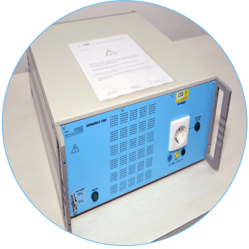
| 3 | Harmonics & Flicker Analyser (6kVA) | Single phase equipment with 16A considered instead of 3 phase equipment |
| 4 | Automotive Transient | Specifications : Test voltage 25V - 1,000V ± 10% Rise time 5ns ± 1.5 ns Verification as As per Annex C of ISO 7637-2:2011 into 50ohm and 1,000ohm load |
| 5 | Conducted Immunity, CRO and Assembly | 1. Conducted Immunity Generator -- Qty 1 2. 6 dB attenuator --Qty 1 3. Injection probe--Qty 1 4. calibration kit --Qty 1 5. 50cm BNC cable --Qty 1 6. CDN--1 set 7. EM clamp 8. Ground Reference planes --1 set 9. Test Tables--1 set 10. RF Cables and Accessories--1 set 11. Oscilloscope 12. Differential probe (± 7kV) Single phase equipment with 16A considered instead of 3 phase equipment |
| 6 | Radiated Emission and Radiated Immunity | 1. Horn Antenna (1.0GHz - 40GHz) Qty 1+1, Active monopole antenna (9KHz - 30Mhz) Qty 1, Active loop antenna (9 kHz - 30 MHz) Qty 1, Van Veen Loop Antenna Qty 1, Biconical & Log periodic antenna (26 MHz–6 GHz) Qty 1+1, Stacked Double log Periodic Antenna (0.7 - 9 GHz ) Qty 1, Double Ridged Broadband Horn (1 GHz...18 GHz) Qty 1, Rs 5,00,000 2. EMI Receiver (20 Hz to 40 GHz) Rs 90,00,000 3. RF Cables 1 set, RF Connectors 1 set, Software & Firmware Rs 25,00,000 4. Filed Monitor Qty 1, Signal Generator (9kHz-6GHz) Qty 1, Power Meter Qty 1, Signal Generator (9kHz-6GHz) Qty 1, Power Meter Qty 1, Average power sensor Qty 2, RF Power Amplifier Qty 1 set, Field probe Qty 2 Rs 5,00,00,000 |
| Conducted Emission | 1. EMI Test Receiver (9kHz - 3GHz) and Pulse Limitier ( 0-30 Mhz)Qty1 - Rs 50,00,000 2. Single Phase LISN (9kHz - 30Mhz, 16A) Qty 1-Rs 5,00,000 3. Coupling Network - Eight wire ISN-Kit Qty 1- Rs 5,00,000 4. Probe set E and H near field measurements,100 KHz – 2 GHz, Battery charger 220V and Active probe [9KHz-30KHz] and Passive Voltage Probe 9 KHz – 30 MHz Qty 1 each -Rs 5,00,000 5. RF-Current probe Qty 1 Rs 2,50,000 6. Absorbing clamp [ 30 – 1000MHz] & 50 ohm with 5 meter long RF cable both end N male connector Qty 1 each -Rs 5,00,000 Single phase equipment with 16A considered instead of 3 phase equipment |
|
| 7 | 10 meter Semi Anechoic chamber | 10 meter Semi Anechoic chamber considered till 40GHz along with Control Room, Amplifier room and one Shielded room. |
| Accessories including ground reference planes, Test Tables, Test jigs, RF cables and accessories, Software and Firmware |

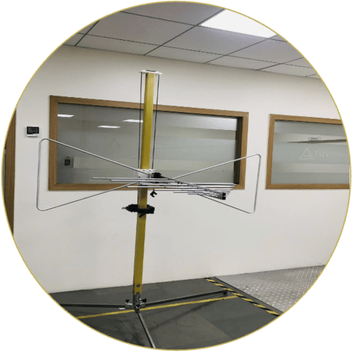
1. Radiated Emission:
Purpose: To measure the electromagnetic field strength of the emissions that are unintentionally generated by your product.
Standard:
EN 55011 / CISPR 11; EN 55016 / CISPR 16; EN 55032 / CISPR 32;
Specification:
Frequency Range : 30MHz to 1 GHz
Measurement Distance : 10 Meter & 3 Meter
Antenna Polarization : Vertical & Horizontal
Antenna Height : 1 Meter to 4 Meter
Measurement Parameters : Peak, Quasi & Avg. Peak
2. Surge Voltage:
Purpose: To find shorts and insulation weaknesses in coils, windings, electric motors, generators, alternators and transformers.
Standard:
EN 61000-4-5 / IEC 61000-4-5
Specification:
Power Line up to : ± 6kV
Signal Line up to : ± 6kV
Phase angle : 0° to 360°
Power Line : Power Line CDN
Signal / Telecom Line : IO CDN / Telecom CDN
Method : Injection
3. Electrostatic Discharge:
Purpose: To evaluate the durability of electronic devices when electrostatic discharge occurs when a person touches them.
Standard:
EN 61000-4-2 / IEC 61000-4-2
Specification:
ESD Generator Parameter : ± 30kV
Support up to
Discharge Type : Contact & Air
Discharge Networks : 150pF/330Ω; 150 pF/2KΩ
330 pF/2K Ω; 330pF/330Ω
4. Conducted Emission:
Purpose: To measure the portion of electromagnetic energy created by the product that is conducted onto the power supply cord.
Standard:
EN 61000-4-2 / IEC 61000-4-2
Specification:
Frequency Range : 9KHz to 30 MHz
Measurement Method : Voltage & Current Probe
Measurement Facility : Shielded Room
Maximum Current Capacity : up to 200A
Measurement Parameters : Peak, Quasi & Avg. Peak
5. Electric Fast Transient
Purpose: To evaluate how electrical and electronic equipment operates under interference
Standard:
EN 61000-4-4 / IEC 61000-4-4
Specification:
Test Voltage : ± 6kV
Repetition Frequency : 5 KHz and 100KHz
Power Line : Power Line CDN
Signal / Telecom Line : Capacitive Coupling Clamp
Method : Injection
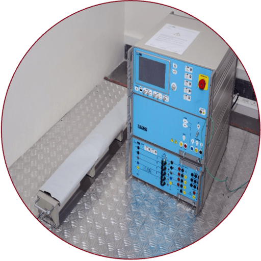
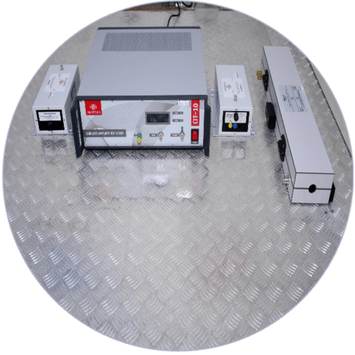
6. Conducted Suscepibility:
Purpose: To evaluate device response to low- mid frequency noise on the conductors.
Standard:
EN 55011 / CISPR 11, EN 55014-1 / CISPR 14-1; EN 55015 / CISPR 15; EN 55016 / CISPR 16; EN 55032 / CISPR 32
Specification:
Frequency Range : 150KHz to 230 MHz
Field Strength : 1Vrms to 30Vrms
Modulation Frequency : 1 Hz to 50KHz (Variable)
Modulation : AM, CW & PM
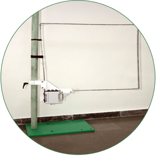
7. Power Frequency Magnetic Field:
Purpose: To simulate the impact of magnetic field (such as those near larger transformers) formed by AC and DC power lines on the equipment undergoing testing
Standard:
EN 61000-4-8 / IEC 61000-4-8
Specification:
Field Strength : 1 A/m to 1000 A/m
Frequency : 50 Hz & 60Hz
Induction Coil : AM, CW & PM
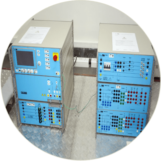
8. Voltage Dips & Interruption:
Purpose: To stimulate the affected of voltage dips, short interruptions or voltage variations of power supply on electronic or electrical products.
Standard:
EN 61000-4-11 / IEC 61000-4-11
Specification:
Input Voltage : AC single phase 265Vac 16A,
AC Three Phase 415Vac 32A
Voltage Dips : 0% to 100%
Phase Angle : 0° to 360°
Test Duration : 0.05msec to 9999sec
Dips Interval : 0.01sec
9. Harmonics Flicker:
Purpose: To stimulate the affected of flicker and harmonics on electrical product which are electrical disturbances that interfere with power supplies.
Standard:
EN 61000-3-2 / IEC 61000-3-2
EN 61000-3-3 / IEC 61000-3-3
Specification:
Input Voltage : Ac Single Phase 300Vac, 16A
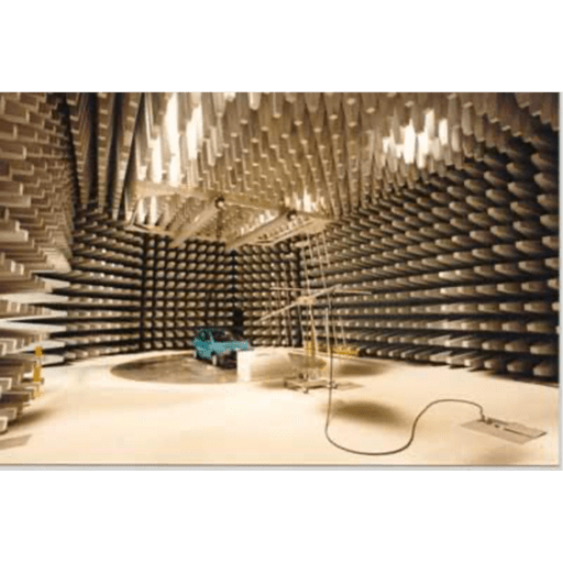
10. Anechoic Chamber:
10 meter Semi Anechoic chamber considered till 40GHz along with Control Room, Amplifier room and one Shielded room.
Accessories including ground reference planes, Test Tables, Test jigs, RF cables and accessories, Software and Firmware
11. Conducted Susceptibility Tests:
Test performance of the equipment in the presence of simulated noise. Objective is to ascertain that EUT shall perform normally under the presence of extraneous noise of certain severity.
Standard:
EN 55011 / CISPR 11, EN 55014-1 / CISPR 14-1; EN 55015 / CISPR 15; EN 55016 / CISPR 16; EN 55032 / CISPR 32
12. Electrical Fast Transients / Burst:
Establishing a common and reproduceable basis for evaluating performance of electronic instrumentation when subjected to repetitive fast transients like those generated by switching of inductive loads, relay contact bouncing or switching of H/V switchgear
Standard:
EN 61000-4-4 / IEC 61000-4-4
Rise Time: 5 n sec.
Duration: 50 n sec.
13. Electrostatic Discharge(ESD):
Used to test the effect of Discharge of Static Electricity when a charged operator touches an equipment
Standard:
EN 61000-4-2 / IEC 61000-4-2
14. Radiated Susceptibility:
To test immunity of equipment against EM fields generated by radio-transmitters like walkie-talkies,radio/TV transmitters as well as industrial unintentional sources
Standard:
IEC 61000-4-3
15. Test Severity Levels:
| S.no | Level | Field Strength(V/m) |
|---|---|---|
| 1. | 1 | 1 |
| 2. | 2 | 3 |
| 3. | 3 | 10 |
| 4. | x | Subject to agreement |
Frequency Range: 80 MHz to 1000MHz
Modulation: 80 % AM @ 1kHz
16. Magnetic Field Immunity Tests:
Power frequency magnetic field (IEC 61000-4-8)
8/20us Pulse magnetic field (IEC 61000-4-9)
1 MHz Damped Oscillatory Magnetic Field (IEC 61000-4-10)
17. Voltage Dips & Interrupts Immunity:
Voltage dips and short interruptions are events that occur due to faults in a power network by sudden changes of large loads. Voltage variations occur by continuously varying loads connected to the power network
Simulates voltage variations, and interruptions caused by short circuits or rapid changes in power. This may cause a sudden and extreme increase in current and a reduction in voltage.
Standards:
EN 61000-4-11 / IEC 61000-4-11
18. Voltage Dips & Interrupts:
Simulates brownouts and blackouts on equipment operation
Standards:
IEC 1000-4-11
19. Flicker Emission:
This test measures voltage fluctuations induced by a device which draws a fluctuating current
Standards:
EN 61000-3-2 / IEC 61000-3-2
EN 61000-3-3 / IEC 61000-3-3
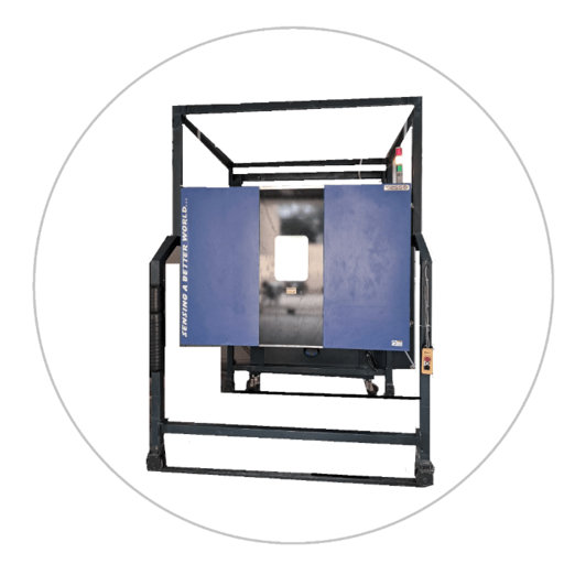
20. Walking Chamber:
Test Perform: To carry out steady state as well as climatic temperature rise test
Standard:
IS 13252/IEC 60695
IS 616/IEC 60065
IEC 61010 & USER SPECIFICATION
Specification:
Inner Space : 2M x 2M x 2M
Temperature : 0 to 100°C
Humidity : 10% to 95%
Control System : Profile controller
Air Circulation : Inner Air circulation
Ramp Rate : 1°C/min
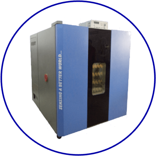
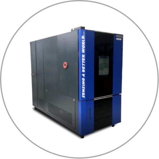
21. Humidity Chamber:
Test Perform: To carry out steady state as well as climatic temperature test
Standard:
IEC 60068-2-1 & IEC 60068-2-2
IS 13252/IEC 60695; IS 616/IEC 60065
IEC 61010 & USER SPECIFICATION
Specification:
Inner Space : 1M x 1M x 1M
Temperature : -65°C to 180°C
Humidity : 10% to 98%
Control System : Profile controller
Air Circulation : Inner Air circulation
Ramp Rate : 3°C/min
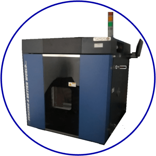
22. Dry Heat Chamber:
Test Perform: To carry out steady state as well as cyclic temperature test
Standard:
IEC 60068-2-2
IS 13252/IEC 60695; IS 616/IEC 60065
IEC 61010 & AS PER CUSTOMER REQUIREMENT
Specification:
Inner Space : 0.8M x 1M x 0.6M
Temperature : amb to 300°C
Control System : Single Profile
controller, PLC
Air Circulation : Inner Air circulation
Ramp Rate : 3°C/min
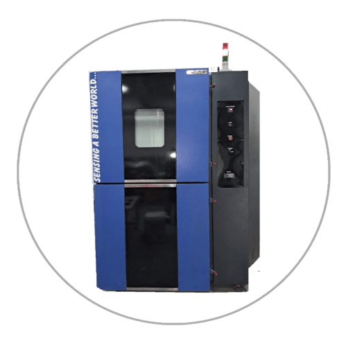
23. Thermal Cyclic:
Test Perform: To carry out steady state as well as cyclic temperature test
Standard:
IEC 60068-2-14 &
AS PER CUSTOMER REQUIREMENT
Specification:
Inner Space : 1M x 1M x 1M
Temperature : -50°C to 180°C
Control System : Profile controller
Air Circulation : Inner Air circulation
Ramp Rate : 10°C/min
24. Thermal Shock:
Test Perform: To carry out rapid change of temperature test
Standard:
IEC 60068-2-14 &
AS PER CUSTOMER REQUIREMENT
Specification:
Inner Space : 0.6M x 0.6M x 0.6M
Temperature : -70°C to 200°C
Control System : Profile controller
Air Circulation : Inner Air circulation
Transfer Time : > 10 sec
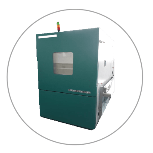
25. Vibration Humidity Chamber:
Test Perform: To carry out climatic temperature test combined with vibration
Standard:
IEC 60068-2-86 &
AS PER CUSTOMER REQUIREMENT
Specification:
Inner Space : 2M x 1.5M x 1M
Temperature : amb to 100°C
Humidity : 10% to 100% Rh
Control System : Profile controller
Air Circulation : Inner Air circulation
Ramp Rate : 1°C/min
Temperature : -70°C to 200°C
Control System : Profile controller
Air Circulation : Inner Air circulation
Transfer Time : > 10 sec